Introduction
In this tutorial we are going to use the LCD Display Module Nokia 5110 for Arduino whi cost around 1.86usd each. We choose this module since it's very cheap and also allow us to have 84x84 with backlight.
You will learn how to use the module in the Raspberry pi using python.
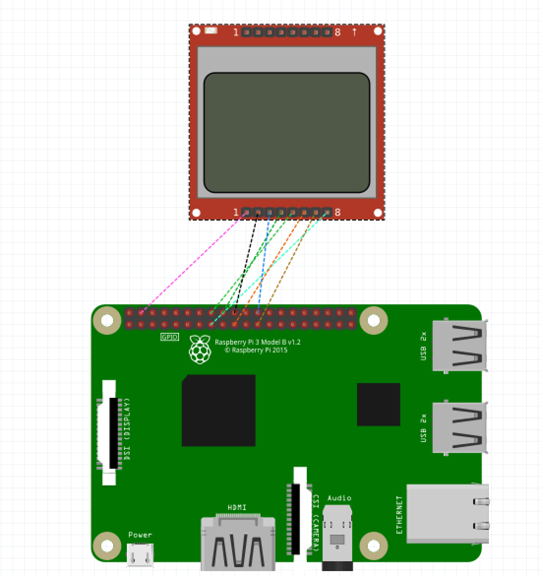
Wiring the LCD module

If you don't understand the wiring in the image, we recomend to open the shema with fritinz. Download fritzing schema for the nokia lcd here.
Some nokia lcd modules could have another pinout, we found that ours uses pin 1 as vcc. Another modules uses pin 6 for vcc!.
We also connected the LED to the GPIO 22 (pin 15) to turn it on and off.
The pin connection for the Nokia LCD using SPIO0 is the following:
- SCLK <-> SPI0 CLK (pin 23)
- DIN <-> SPI0 MOSI (pin 19)
- SCE (CS) <-> SPI0 CS0 (pin 24)
- RST <-> Any GPIO we choose: GPIO23 (pin 18)
- DC <-> Any GPIO we choose GPIO24 (pin 16)
- LED <-> Any GPIP we choose GPIO22 (pin 15)
Installing the software
For using the lcd module on the raspberry pi we will use python. Install de libraries with:
sudo apt-get install -y python3 python3-pip python-dev python-imaging
sudo apt-get install build-essential python-dev python-smbus python-pip
pip3 install Adafruit_BBIO pygpio char_lcd
We are going to use adafruit scroller animation as an example, first download the example:
wget https://github.com/adafruit/Adafruit_Nokia_LCD/blob/master/examples/animate.py
python animate.py
Open the file animate.py and check the wiring is the correct one:
# Raspberry Pi hardware SPI config:
DC = 23
RST = 24
SPI_PORT = 0
SPI_DEVICE = 0
Those values corresponds to the raspberry pi pins. if you are using SPI1 check the correct port.
Here is a working wiring using SPI1 to connect Nokia LCD:
- SCLK <-> SPI1 CLK (pin 40)
- DIN <-> SPI1 MOSI (pin 38)
- CS <-> SPI1 CS0 (pin36)
- RST <-> Any GPIO we choose: GPIO13 (pin 33)
- DC <-> Any GPIO we choose GPIO26 (pin 37)
- LED <-> Any GPIP we choose GPIO6 (pin 31)
You need to change the code to use the correct GPIO
# Raspberry Pi hardware SPI config:
LED = 6
DC = 26
RST = 13
SPI_PORT = 0
SPI_DEVICE = 0
